Next: “Nonlocal” model for SHCC Up: Material models specific to Previous: Fixed crack model for
This material model is an extension of the ConcreteFCM described in Section 1.6.11.
It is possible to choose from three different “classes” of fibers. This choice is controlled by keyword fiberType: 0 = continuous aligned fibers (CAF), 1 = short aligned fibers (SAF) and 2 = short random fibers (SRF). Currently, it is not possible to combine more classes of fibers in one material model.
All of the above-mentioned fiber types are further defined by the material properties and geometry. Fiber quantity is captured by the dimensionless volume fraction Vf (as decimal). All fibers are assumed to have a circular cross-section (shape factor for shear kfib with default value 0.9) and to possess the same geometry characterized by the diameter Df and length Lf.
The overall elastic stiffness of the fiber-reinforced composite is calculated as a weighted average of the moduli of matrix ![]() and fibers
and fibers ![]() and the Poisson's ratio is considered to be equal to the Poisson's ratio of the matrix. Similarly to ConcreteFCM, cracking is initiated once the tensile stress
and the Poisson's ratio is considered to be equal to the Poisson's ratio of the matrix. Similarly to ConcreteFCM, cracking is initiated once the tensile stress ![]() in matrix reaches the tensile strength
in matrix reaches the tensile strength ![]() .
.
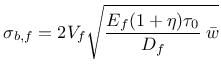
The nominal bridging stress for continuous aligned fibers which are not perpendicular to the crack plane
![]() can be very easily obtained by multiplying the nominal bridging stress for perpendicular fibers
can be very easily obtained by multiplying the nominal bridging stress for perpendicular fibers
![]() by two terms: the first one reflecting lower volume of inclined fibers passing through the crack plane and the second one capturing the snubbing effect:
by two terms: the first one reflecting lower volume of inclined fibers passing through the crack plane and the second one capturing the snubbing effect:
| (179) |
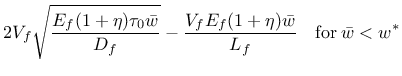
For the CAF perpendicular to the crack, the nominal bridging stress can be derived as
 |
(180) |
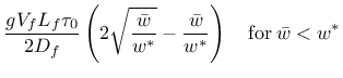
For SRF the nominal bridging stress is
 |
(181) | ||
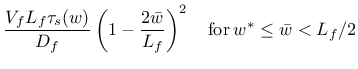 |
(182) | ||
| (183) |
![$w^* = \left(L_f^2 \tau_0 \right)/[(1+\eta) E_f D_f]$](img794.png) ;
;
Larger pull-out displacements can lead to significant physical changes in the fiber surface which can result into changes in the bond shear stress. This phenomenon is captured by function ![]() relating the frictional bond to the crack opening and is implemented in three alternative formulations. (In order to keep
relating the frictional bond to the crack opening and is implemented in three alternative formulations. (In order to keep
![]() use fssType = 0.) In conventional FRC with ordinary concrete matrix, the frictional bond usually decreases with increasing slip. To capture this type of behavior we adopt the function proposed by Sajdlová (activated with fssType = 1) reads
use fssType = 0.) In conventional FRC with ordinary concrete matrix, the frictional bond usually decreases with increasing slip. To capture this type of behavior we adopt the function proposed by Sajdlová (activated with fssType = 1) reads
![$\displaystyle \tau_s(w) = \tau_0 \left[ 1 + \mathrm{sign}(b_0) \left( 1 - \exp \left( -\frac{\vert b_0\vert w}{D_f} \right) \right) \right]$](img798.png) |
(184) |
![$\displaystyle \tau_s(w) = \tau_0 \left[ 1 + b_1 \frac{w}{D_f} + b_2 \left( \frac{w}{D_f} \right)^2 + b_3 \left( \frac{w}{D_f} \right)^3 \right]$](img800.png) |
(185) |
![$\displaystyle \tau_s(w) = \tilde{\tau}_0 + \tau_0 \left[ b_1 \frac{ \tilde{w} }...
...ilde{w} }{D_f} \right)^2 + b_3 \left( \frac{ \tilde{w} }{D_f} \right)^3 \right]$](img801.png) |
(186) |
The bridging stress for SRF is defined as
 |
(187) | ||
 |
(188) | ||
| (189) |
 |
(190) |
It is possible to delay the activation of the stress in fibers using prameteter fibreActivationOpening which can be imagined as a “lag” of the fiber-related crack opening behind the matrix-related crack opening.
During unloading the stress in fibers does not decrease linearly to origin. Current implementation uses a power function
 |
(191) |
The influence of crack opening and sliding on the bridging shear stress only due to fibers is expressed as
 |
(192) |
It has been found that in some high performance fiber reinforced cement composites, fibers rupture when cracks are exposed to shearing. This phenomenon is modeled by damage parameter ![]() , which accounts for the ratio of ruptured fibers and varies between the values of 0 and 1. It is assumed that
, which accounts for the ratio of ruptured fibers and varies between the values of 0 and 1. It is assumed that ![]() depends on the maximum shear strain sustained by the protruding portions of bridging fibers throughout the loading history. This crack shear strain can be expressed as:
depends on the maximum shear strain sustained by the protruding portions of bridging fibers throughout the loading history. This crack shear strain can be expressed as:
 |
(193) |
where ![]() is the crack sliding displacement (CSD) and and
is the crack sliding displacement (CSD) and and ![]() is the maximum value of the crack opening displacement of the i-th crack. This means that the damage does not grow if the crack closes (crack opening decreases). If more cracks exist, the maximum contribution is considered.
is the maximum value of the crack opening displacement of the i-th crack. This means that the damage does not grow if the crack closes (crack opening decreases). If more cracks exist, the maximum contribution is considered.
Two different one-parameter damage evolution laws are currently implemented. For fDamType = 0 the damage is deactivated, with fDamType = 1 damage is described by
 |
(194) |
 |
(195) |
Since damage reduces the number of crack-bridging fibers, which is proportional to the fiber volume fraction, its effect can be suitably implemented by introducing the effective volume fraction
| (196) |
The material parameters are summarized in Tables 42 (matrix) and 43 (fiber extension).
Sample syntax for a fixed crack model reinforced with fibers with volume density 24 kN/m![]() , thermal dilation coefficient
, thermal dilation coefficient
![]() K
K![]() , Young's modulus of the matrix 20 GPa, Poisson's ratio of matrix 0.2, fracture energy of matrix 100 N/m, tensile strength of matrix 2 MPa, linear tension softening, constant shear retention factor
, Young's modulus of the matrix 20 GPa, Poisson's ratio of matrix 0.2, fracture energy of matrix 100 N/m, tensile strength of matrix 2 MPa, linear tension softening, constant shear retention factor
![]() , unlimited shear strength (shearStrengthType = 0), continuous aligned fibers, fiber volume 2%, fiber diameter 0.04 mm, Young's modulus of fibers 20 GPa, shear modulus of fibers 1 GPa, fiber-matrix bond strength 1 MPa, snubbing coefficient 0.7, shear correction coefficient 0.9, deactivated fiber damage, fiber act if COD exceeds 10
, unlimited shear strength (shearStrengthType = 0), continuous aligned fibers, fiber volume 2%, fiber diameter 0.04 mm, Young's modulus of fibers 20 GPa, shear modulus of fibers 1 GPa, fiber-matrix bond strength 1 MPa, snubbing coefficient 0.7, shear correction coefficient 0.9, deactivated fiber damage, fiber act if COD exceeds 10 ![]() m (with smoothing from
m (with smoothing from
![]()
![]() m), fiber orientation at 45 degrees in x-y plane, automatic evaluation of crack spacing from composition; the analysis uses [m], [MPa] and [MN]:
m), fiber orientation at 45 degrees in x-y plane, automatic evaluation of crack spacing from composition; the analysis uses [m], [MPa] and [MN]:
FRCFCM 1 d 24.e-3 talpha 12.e-6 E 20000. n 0.2 Gf 100e-6 ft 2.0
softType 2 shearType 1 beta 0.05 FiberType 0 Vf 0.02 Df 0.04e-3
Ef 20000. Gfib 1000. tau_0 1. FSStype 0 f 0.7 kfib 0.9 fDamType 0
fibreactivationopening 10.e-6 dw0 2.e-6 dw1 1.e-6 orientationVector 3 1. 1. 0. computeCrackSpacing
Borek Patzak