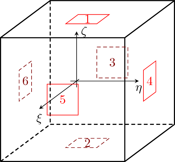
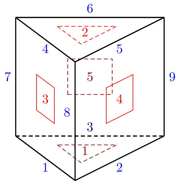
Figure 16: LSpace element (Node numbers in black, side numbers in blue, and surface numbers in red).
This section contains description of continuum elements.
Implementation of Linear 3d eight - node finite element. Each node has 3 degrees of freedom. The element features are summarized in Table 38.
| Keyword | lspace |
| Description | Linear isoparametric brick element |
| Specific parameters | [NIP #(in)] |
| Parameters | NIP: allows to set the number of integration points (possible completions are 1, 8 (default), or 27). |
| Unknowns | Three dofs (u-displacement, v-displacement, w-displacement) are required in each node. |
| Approximation | Linear approximation of displacement and geometry. |
| Integration | Full integration of all strain components. |
| Features | Supports adaptivity, geometric nonlinearity, and layered cross section support |
| CS properties | - |
| Loads | - |
| Nlgeo | 0,1,2. |
| Status | Reliable |
| Tests/Examples | tests/sm/patch302.in, tests/sm/compoDamMat.in, tests/sm/deadweight02.in |
Implementation of 3d brick eight - node linear approximation element with selective integration of deviatoric and volumetric strain contributions (B-bar formulation) for incompressible problems. Features and description identical to conventional lspace element, see section 2.8.1.
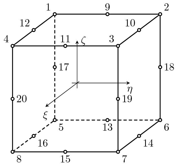
Implementation of quadratic 3d 20-node finite element. Each node has 3 degrees of freedom. The element features are summarized in Table 39.
| Keyword | qspace |
| Description | Quadratic isoparametric brick element |
| Specific parameters | [NIP #(in)] |
| Parameters | NIP: allows to set the number of integration points (possible completions are 1, 8 (default), or 27). |
| Unknowns | Three dofs (u-displacement, v-displacement, w-displacement) are required in each node. |
| Approximation | Quadratic approximation of displacement and geometry. |
| Integration | Full integration of all strain components. |
| Features | Layered cross section support. |
| CS properties | - |
| Loads | - |
| Nlgeo | 0,1,2. |
| Status | Reliable |
| Tests/Examples | |
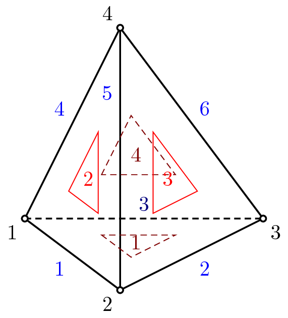
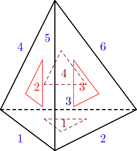
Implementation of tetrahedra four-node finite element. Each node has 3 degrees of freedom. The element features are summarized in Table 40. Following node numbering convention is adopted (see also Fig. 18):
Select a face that will contain the first three corners. The excluded corner will be the last one.
Number these three corners in a counterclockwise sense when looking at the face from the excluded corner.
| Keyword | LTRSpace |
| Description | Linear tetrahedra element |
| Specific parameters | - |
| Unknowns | Three dofs (u-displacement, v-displacement, w-displacement) are required in each node. |
| Approximation | Linear approximation of displacements and geometry using linear volume coordinates. |
| Integration | Full integration of all strain components using four point Gauss integration formula. |
| Features | Adaptivity support, Geometric nonlinearity support. |
| CS properties | - |
| Loads | Surface and Edge loadings supported. |
| Nlgeo | 0,1,2. |
| Status | Reliable |
| Tests/Examples | |
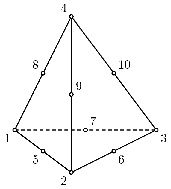
Implementation of tetrahedra ten-node finite element. Each node has 3 degrees of freedom. The element features are summarized in Table 41. Following node numbering convention is adopted (see also Fig. 19):
| Keyword | QTRSpace |
| Description | 3D tetrahedra element with quadratic interpolation |
| Specific parameters | [NIP #(in)] |
| Parameters | NIP: allows to alter the default integration formula (possible completions are 1, 4 (default), 5, 11, 15, 24, and 45 point intergartion formulas). |
| Unknowns | Three dofs (u-displacement, v-displacement, w-displacement) are required in each node. |
| Approximation | Quadratic approximation of displacements and geometry using linear volume coordinates. |
| Integration | Full integration of all strain components using four point Gauss integration formula. |
| Features | - |
| CS properties | - |
| Loads | - |
| Nlgeo | 0,1,2. |
| Status | Reliable |
| Tests/Examples | - |
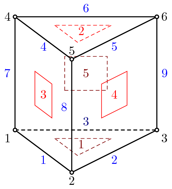
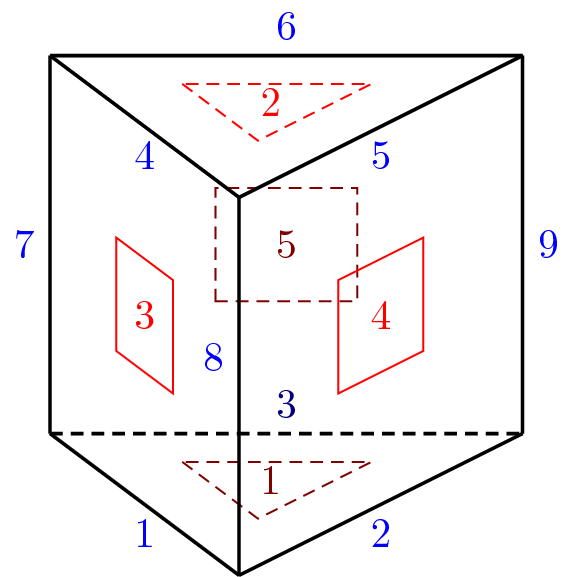
Implementation of wedge six-node finite element. Each node has 3 degrees of freedom. The element features are summarized in Table 42. Following node numbering convention is adopted (see also Fig. 20):
| Keyword | LWedge |
| Description | 3D wedge six-node finite element with linear interpolation |
| Specific parameters | [NIP #(in)] |
| Parameters | NIP: allows to alter the default integration formula (possible completions are 2 (default) and 9 point integration formulas). |
| Unknowns | Three dofs (u-displacement, v-displacement, w-displacement) are required in each node. |
| Approximation | Linear approximation of displacements and geometry. |
| Integration | Full integration of all strain components using four point Gauss integration formula. |
| Features | Layered cross section support. |
| CS properties | - |
| Loads | - |
| Nlgeo | 0,1,2. |
| Status | Reliable |
| Tests/Examples | - |
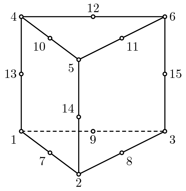
Implementation of wedge fifteen-node finite element. Each node has 3 degrees of freedom. The element features are summarized in Table 43. Following node numbering convention is adopted (see also Fig. 21):
| Keyword | QWedge |
| Description | 3D wedge six-node finite element with quadratic interpolation |
| Specific parameters | [NIP #(in)] |
| Parameters | NIP: allows to alter the default integration formula (possible completions are 2 (default) and 9 point integration formulas). |
| Unknowns | Three dofs (u-displacement, v-displacement, w-displacement) are required in each node. |
| Approximation | Quadratic approximation of displacements and geometry. |
| Integration | Full integration of all strain components using four point Gauss integration formula. |
| Features | Layered cross section support. |
| CS properties | - |
| Loads | - |
| Nlgeo | 0,1,2. |
| Status | Reliable |
Selected 3D elements (bricks and wedge geometries) support using the LayeredCrossSection model to define layer stack as a sequence of individual layers. Individual layers are assumed to lie in element parametric ξ -η plane and are stacked along parametric ζ coordinate of the element. The direction of parametric coordinates is determined by element node numbering convention, see figures with element geometries above. Note, that the stacking direction is in general the function of element geometry.
It is important to understand concept of element and material coordinate systems.
The element coordinate system (elemCS) coincides, by default, with the global coordinate system. The user-defined element coordinate system can be defined using lcs parameter. The lcs parameter defines an array of size 6, where the first 3 components define direction of local element-axis and remaining 3 components define direction of local element y-axis. The local element z axis is computed using vector product ez = ex × ey.
The material properties of each layer are defined in material coordinate system (matCS). Also the solver output for
individual layers is done in matCS. By default, the material coordinate system coincides with global coordinate
system. Additionally, the material coordinate system for individual layer can be rotated around material CS z-axis
by angle, defined by layered cross section rotations keyword. This array parameter allows to define
rotation angle for individual layers and should be defined in degrees not radians. If matcs element keyword
is present, but no lcs element record is defined, then the following definition of elemCS is assumed:
ex = { ,
, ,
, },h = {
 ,
, ,
, },ez = ex × h,ey = ez × ex, where ξ,η,ζ are
parametric element coordinates. The strains and stresses in individual layers are always reported in material
coordinate system. LayeredCS integration The layered cross section integration can be set up using number of
integrations points in layer plane (nintegrationpoints parameter ) and using number of integration points per layer
thickness (layerintegrationpoints parameter).
},ez = ex × h,ey = ez × ex, where ξ,η,ζ are
parametric element coordinates. The strains and stresses in individual layers are always reported in material
coordinate system. LayeredCS integration The layered cross section integration can be set up using number of
integrations points in layer plane (nintegrationpoints parameter ) and using number of integration points per layer
thickness (layerintegrationpoints parameter).