Inelastic analysis of steel joint behavior
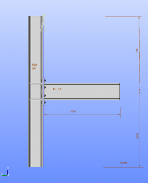
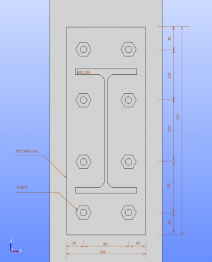
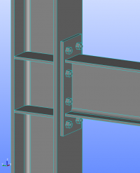
The geometry of steel joint is illustrated on the following figures.
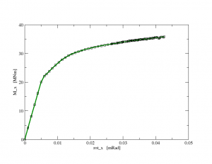
The purpose of the simulation was to obtain moment-rotation working diagram of the joint loaded by the moment at the end of the vertical beam, while the ends of the columns were clamped. In order to capture the characteristic behavior, the nonlinear plastic Mises model has been used with the following parameters: Young modulus: 210000 MPa, Poisson ratio 0.3, Yield stress 275 MPa, and a small value of isotropic hardening moduli equal to 10 MPa was used. The contact between column and the joint plate has been modeled using interface elements, to model compression only behavior with very high stiffness and stress free behaviour in tension.
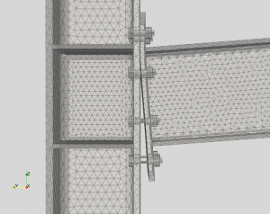
The geometrical model and mesh has been created in Salome and converted to oofem using unv2oofem tool. The FE mesh consist of 22642 nodes and 75105 element (terrahedra elements with linear interpolation). The deformed shape at the end of analysis (deformations scaled 2x) is illustrated on the following figure, clearly showing the contact mechanics.
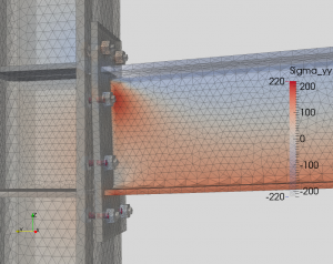 | 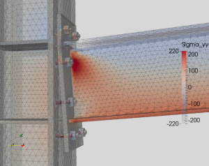 |
| The profiles of stress in y-direction on deformed configuration. | The profiles of stress in y-direction on deformed configuration. |
Finally the obtained load-displacement diagram is shown below.
Download: Salome model and oofem input
— Borek Patzak 2014/05/14 13:47
