Temperature evolution due to hydration in insulated column
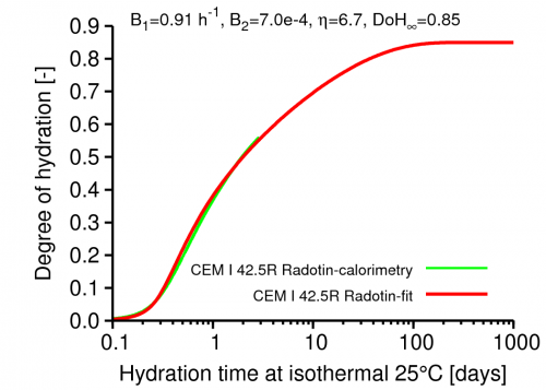
First, affinity hydration model was calibrated to released heat from isothermal calorimetry. Cement CEM I 42.5R from Radotín, Czech Republic was used for this purpose, see the Figure below.
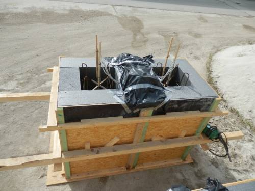
The same cement was used in concrete production thus parameters of the affinity model remained the same. A column 0.5 x 0.5 x 1.5 m was cast in two steps with approximately 3 days time lag between casting. Thermal insulation 0.25 m thick was present on all vertical faces of the column. Bottom and top parts had equal 0.75 m length. Top parts were covered by a foil to prevent water evaporation and excessive heat loss. Figure below shows experimental setup.
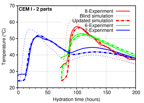
Simulations reflected external fluctuation of ambient temperature and casting sequence. During the first simulation, so called blind stage, no experimental results were provided and other parameters of the model were estimated. The second stage calibrated especially heat transfer coefficients and extra induction time. Temperature sensors 2, 6, 8 were located on central vertical axis at distances 0.375, 0.775 and 1.125 m from bottom. The last two sensors were located in the upper part. Figure below displays results from blind and updated stages. Animation is provided as well. Number of nodes 8381, linear brick elements 7168, time integration step 2 hours, 100 steps, computation time 17 minutes.
Animation of temperature field in the column.
Created 11/2012 by Vít Šmilauer. Acknowledgements belong to Jan L. Vítek and K. Chmelíková who conducted experimental part.


