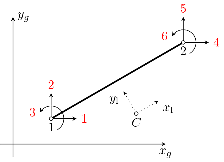
Figure 3: Beam2d element. Definition of local c.s.(a) and definition of local end forces and local element dofs
(b).
Beam element for 2D analysis, based on Timoshenko hypothesis. Structure should be defined in x,z plane. The internal condensation of arbitrary DOF is supported and is performed in local coordinate system. On output, the local end displacement and local end forces are printed. The element features are summarized in Table 4.
| Keyword | beam2d |
| Description | 2D beam element |
| Specific parameters | [dofstocondense #(ia)] |
| Parameters | dofstocondense: allows to specify local element dofs that will be condensed. The numbering of local element dofs is shown in fig. 3. The size of this array should be equal to number of local element dofs (6) and nonzero value indicates the corresponding dof will be condensed. |
| Unknowns | Three dofs (u-displacement, w-displacement, y-rotation) are required in each node. |
| Approximation | Cubic approximations of lateral displacement and rotation are used. For longitudinal displacement the linear one is assumed. |
| Integration | Exact. |
| Features | Full dynamic analysis support. Linear stability analysis support. |
| CS properties | Area,inertia moment along y-axis (iy parameter) and equivalent shear area (shearareaz parameter) should be specified. |
| Loads | Constant and linear edge loads are supported, shear influence is taken into account. Edge number should be equal to 1. Temperature load is supported, the first coefficient of temperature load represent mid-plane temperature change, the second one represent difference between temperature change of local z+ and local z- surfaces of beam (in local coordinate system). Temperature load require that the “thick” property of cross section model is defined. |
| Status | Reliable |
| Tests/Examples | tests/sm/beam2d_1.in, tests/sm/beam2d_2.in, tests/sm/beam2d_3.in |
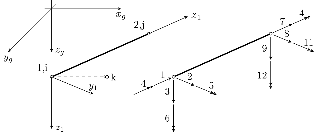
Beam element for 3D linear analysis, based on Timoshenko hypothesis. The internal condensation of arbitrary DOF is supported and is performed in local coordinate system. On output, the local end-displacement and local end-forces are printed. Requires the local coordinate system to be chosen according to main central axes of inertia. Local element coordinate system is determined by the following rules:
let first element node has following coordinates (xi,yi,zi) and the second one (xj,yj,zj),
direction vector of local x-axis is then a1 = (xj - xi,yj - yi,zj - zi),
local y-axis direction vector lies in plane defined by local x-axis direction vector (a1) and given point (k-node with coordinates (xk,yk,zk)) - so called reference node,
local z-axis is then determined as vector product of local x-axis direction vector (a1) by vector (xk - xi,yk - yi,zk - zi),
local y-axis is then determined as vector product of local z-axis direction vector by local x-axis direction vector.
The element features are summarized in Table 5.
| Keyword | beam3d |
| Description | 3D beam element |
| Specific parameters | refnode #(in) [dofstocondense #(ia)] |
| Parameters | refnode: sets reference node to determine the local coordinate system of element. |
| dofstocondense: allows to specify local element dofs that will be condensed. The numbering of local element dofs is shown in fig. 4. The size of this array should be equal to number of local element dofs (12) and nonzero value indicates the corresponding dof will be condensed. |
|
| Unknowns | Six dofs (u,v,w-displacements and x,y,z-rotations) are required in each node. |
| Approximation | Cubic approximations of lateral displacement and rotation (along local y,z axes) are used. For longitudinal displacement and the rotation along local x-axis (torsion) the linear approximations are assumed. |
| Integration | Exact. |
| Features | Full dynamic analysis support. Linear stability analysis support. |
| CS properties | Area, inertia moment along y and z axis (iy and iz parameters), torsion inertia moment (ik parameter) and either cross section area shear correction factor (beamshearcoeff parameter) or equivalent shear areas (shearareay and shearareaz parameters) are required. These cross section properties are assumed to be defined in local coordinate system of element. |
| Loads | Constant and linear edge loads are supported. Edge number should be equal to 1. Temperature load is supported, the first coefficient of temperature load represent mid-plane temperature change, the second one represent difference between temperature change of local z+ surface and local z- surface surface of beam and the third one represent difference between temperature change of local y+ surface and local y- surface of beam. Requires the “thick” (measured in direction of local z axis) and “width” (measured in direction of local y axis) cross section model properties to be defined. |
| Status | Reliable |
| Tests/Examples | tests/sm/beam3d_1.in, tests/sm/beam3d_2.in, tests/sm/beam3d_3.in |