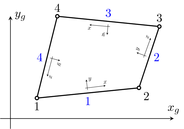
Figure 5: Lattice2d element. Node numbering, DOF numbering and definition of integration point C.
Represents two-node lattice element. Each node has 3 degrees of freedom. The element is based on the Rigid Body Spring Model originally developed by Kawai and later delveloped by Bolander for modelling fracture in concrete. The main idea is to model the elastic and inelastic response of a connection of two nodes by a set of springs located at the contact facet of two rigid bodies, which is the mid-cross-section of the element. Displacement jumps are computed at the mid-cross-section, which are smeared out over the element length in the form of strains. The element is defined in x,y plane (see Figure 5). The element features are summarized in Table 6.
| Keyword | lattice2d |
| Description | 2d lattice element |
| Specific parameters | thick #(rn) width #(rn) gpCoords #(ra) |
| Parameters | thick: defines the out of plane (z-direction) thickness |
| width: defines the width of the midpoint cross-section in the x-y plane with the point C at its centre |
|
| gpCooords: array of the coordinates of the integration point C in the global coordinate system |
|
| Unknowns | Three dofs (u-displacement, v-displacement, w-rotation) are required in each node. |
| Tests/Examples | tests/sm/lattice2drandom.in, tests/sm/latticedamagevisco_mps_1.in |
The theory of lattice2d is described in the paper “P. Grassl and M. Jirásek. Meso-scale approach to modelling the fracture process zone of concrete subjected to uniaxial tension. International Journal of Solids and Structures. Volume 47, Issues 7-8, pp. 957-968, 2010.”
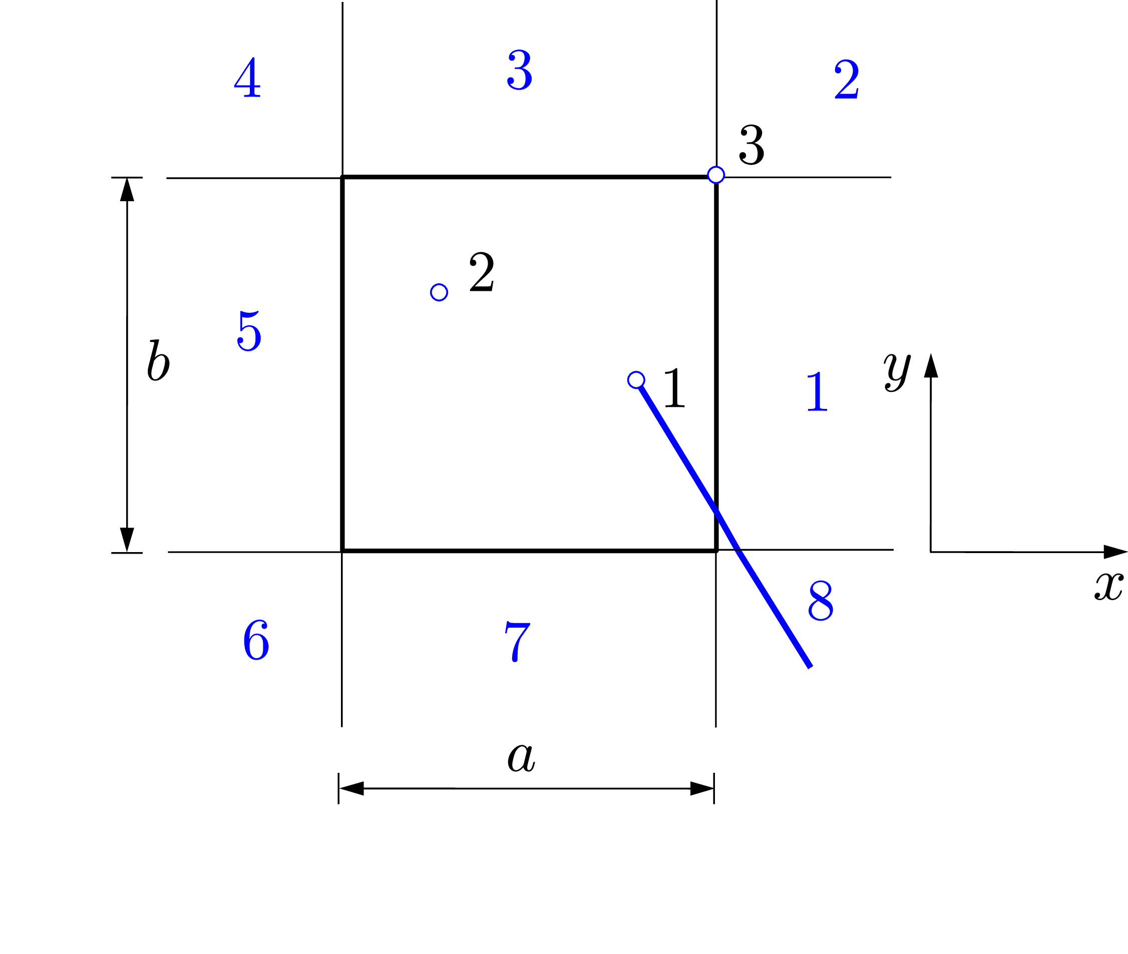
Represents three-node lattice element for boundary of 2d periodic cells. The first two nodes have 3 degrees of freedom as for the element lattice2d. The third node is used to control the loading of the periodic cell. It has three components which are displacements, which are produces of the macroscopic (average) strain components and length of the peridodic cell as aExx, bExx and bGxy and the length of the periodic cell. The DOFs of the node that lies outside the periodic are computed from those of the periodic image inside the cell and the DOFs at the third node (Figure 6). The coordinates x and y of the third node are the lengths a and b of the periodic cell, respectively. The element is defined in x,y plane. The strain components at the additional node have the meaning of average strains in the periodic cell. The specific input parameters for this element in addition to those used for lattice2d are shown in Table ??.
| Keyword | latticeboundary2D |
| Description | 2d lattice boundary element |
| Specific parameters | location #(in) |
| Parameters | location: number between 1 and 8 which specifies the location of the node with respect to the periodic cell. |
| Unknowns | Nine DOFs are required, which are u-displacement, v-displacement and w-rotation at nodes 1 and 2, and aExx, bEyy and bGxy at node 3. |
| Tests/Examples | |
| Reference | [4] |
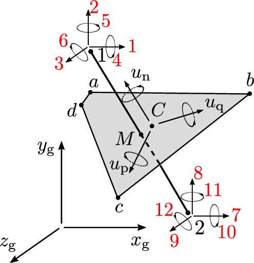
Lattice3d represents a two-node 3d lattice element. Each node has six degrees of freedom as shown in Figure 7. The element is based on the Rigid Body Spring Model originally developed by Kawai and later delveloped by Bolander for modelling fracture in concrete. The main idea is to model the elastic and inelastic response of a connection of two nodes by a set of springs located at the contact facet of two rigid bodies, which is the mid-cross-section of the element. The properties of the mid-cross-section are internally computed from its vertices which are given as input in the global coordinate sytem. Displacement jumps are computed at the mid-cross-section, which are smeared out over the element length in the form of strains. The input parameters for this element are shown in Table 8.
| Keyword | lattice3d |
| Description | 3d lattice element |
| Specific parameters | polycoords #(ra) couplingflag #(in) couplingnumbers #(ra) pressures #(ra) mlength #(rn) |
| Parameters | polycooords: array of the coordinates of the vertices of the mid-cross-section of the lattice element in the global coordinate system. |
| couplingflag: flag (optional parameter. Default is 0) which activates coupling with a transport lattice element. |
|
| couplingnumbers: array of numbers of transport lattice elements (optional parameter), which are coupled with the 3d lattice element. |
|
| pressures: array of pressure values (optional parameter), which are used to consider influence of fluid pressure on mechanical response. |
|
| mlength: minimum length (optional parameter) is used to check if the cross-section of the element is not too small. Default value is 1.e-20. |
|
| Unknowns | Six dofs (u-displacement, v-displacement, w-displacement, u-rotation, v-rotation and w-rotation) are required in each node. |
| Tests/Examples | tests/sm/lattice3d1.in, tests/sm/lattice3d2.in, tests/sm/lattice3d3.in |
| Reference | [5] |
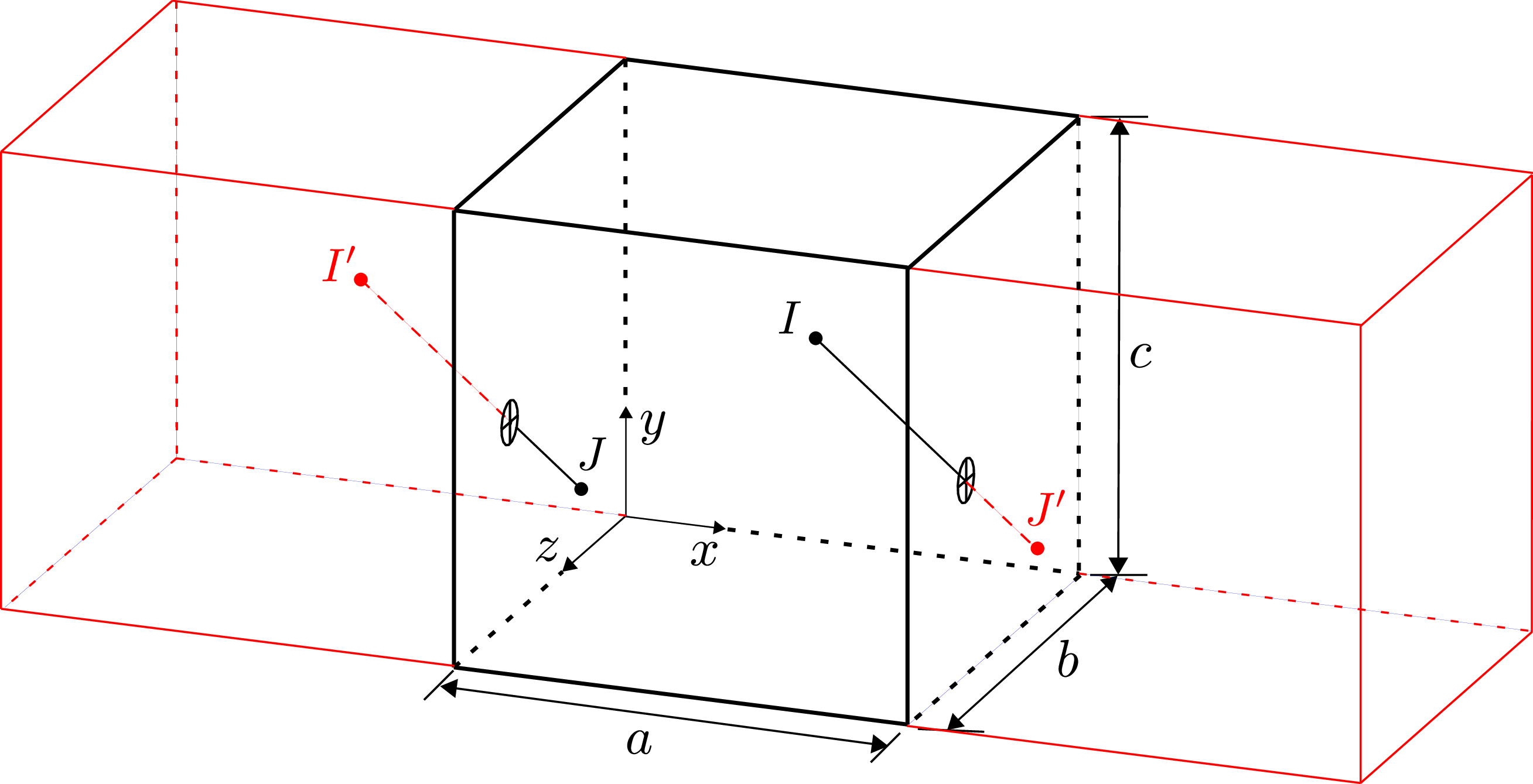
This element represents a three-noded 3d lattice element for boundaries of 3d periodic cells. The first two nodes have 6 degrees of freedom as for the element lattice3d. The third node is used to control the loading of the periodic cell using three normal (aExx, bEyy and zEzz) and three shear strain (cGyz, cGxz, bGxy) components. Here, a, b and c are the three dimensions of the periodic cell. The DOFs of the node that lies outside the periodic are computed from those of the periodic image inside the cell and the DOFs at the third node (Figure 8). The connection between periodic nodes is defined as
| (1) |
Here, x′ and x are the nodes inside and outside, respectively, and M is the translation matrix, for which the input is provided in the form of a location parameter as shown in Table 9.
| Keyword | lattice3dboundary |
| Description | 3d lattice boundary element |
| Specific parameters | location #(in) |
| Parameters | location: array of two numbers between number between 1 and 26, which specifies the location of the two nodes with respect to the 3d periodic cell. |
| Unknowns | Six dofs (u-displacement, v-displacement, w-displacement, u-rotation, v-rotation and w-rotation) are required in each of the first two node. Node 3 requires the 6 quantities to control the periodic cell aExx, bEyy, zEzz, cGyz, cGxz and bGxy |
| Tests/Examples | |
| Reference | [6] |
This element represents a two-node 3d link element connecting 3d beam and 3d lattice elements. Each node has six degrees of freedom. The input parameters for this element are shown in Table 10.
| Keyword | latticelink3d |
| Description | 3d lattice link element |
| Specific parameters | length #(rn) diameter #(rn) dirvector #(ra) l_end #(rn) |
| Parameters | length: bond length |
| diameter: diameter | |
| dirvector: direction vector in which bond-slip occurs. |
|
| l_end: array of pressure values (optional parameter), which are used to consider influence of fluid pressure on mechanical response. |
|
| mlength: minimum length (optional parameter) is used to check if the cross-section of the element is not too small. Default value is 1.e-20. |
|
| Unknowns | Six dofs (u-displacement, v-displacement, w-displacement, u-rotation, v-rotation and w-rotation) are required in each node. |
| Tests/Examples | |
| Reference | [7] |
Represents three-node 3d boundary link element connecting 3d beam and 3d lattice elements. The first two nodes have the same meaning as for latticelink3d. The third node is used to control the loading of the periodic cell using three normal (xx, yy and zz) and three shear strain (yz, xz, xy) components. The specific input parameters for this element in addition of those for latticelink3d are shown in Table 11.
| Keyword | latticelink3dboundary |
| Description | 3d lattice link boundary element |
| Specific parameters | location #(in) rn |
| Parameters | location: |
| Unknowns | Six dofs (u-displacement, v-displacement, w-displacement, u-rotation, v-rotation and w-rotation) are required in each node. |
| Reference | [7] |
