Figure 13: Quad1PlaneStrain element. Node numbering, Side numbering and definition of local edge c.s.(a).
Represents isoparametric four-node quadrilateral plane-strain finite element. Each node has 2 degrees of freedom. Structure should be defined in x,y plane. The nodes should be numbered anti-clockwise (positive rotation around z-axis). The element features are summarized in Table 21.
| Keyword | quad1planestrain |
| Description | 2D linear quadrilateral plane-strain element |
| Specific parameters | [NIP #(in)] |
| Parameters | NIP: allows to set the number of integration points for integration of membrane terms. |
| Unknowns | Two dofs (u-displacement, v-displacement) are required in each node. |
| Approximation | Linear approximation of displacements and geometry. |
| Integration | Integration of membrane strain terms using gauss integration formula in 4 (the default), 9 or 16 integration points. The default number of integration points used can be overloaded using NIP parameter. Reduced integration for shear terms is employed. Shear terms are always integrated using 1 point integration rule. |
| Features | Nonlocal constitutive support, Adaptivity support. |
| CS properties | Cross section thickness is required. |
| Loads | Body loads are supported. Boundary loads are supported and computed using numerical integration. The side numbering is following. Each i-th element side begins in i-th element node and ends on next element node (i+1-th node or 1-st node, in the case of side number 4). The local positive edge x-axis coincides with side direction, the positive local edge y-axis is rotated 90 degrees anti-clockwise (see fig. (13)). |
| Nlgeo | 0. |
| Status | Reliable |
| Tests/Examples | |
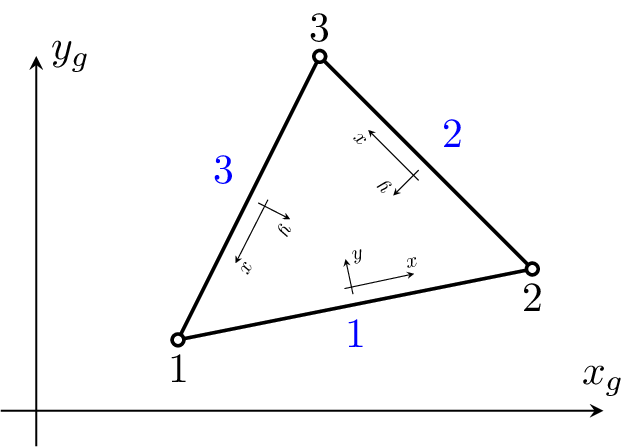
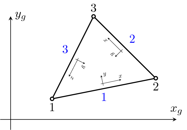
Implements an triangular three-node constant strain plane-strain finite element. Each node has 2 degrees of freedom. The node numbering is anti-clockwise. The element features are summarized in Table 22.
| Keyword | trplanestrain |
| Description | 2D linear triangular plane-strain element |
| Specific parameters | - |
| Unknowns | Two dofs (u-displacement, v-displacement) are required in each node. |
| Approximation | Linear approximation of displacements and geometry. |
| Integration | Integration of membrane strain terms using one point gauss integration formula. |
| Features | Nonlocal constitutive support. Edge load support, Adaptivity support. |
| CS properties | Cross section thickness is required. |
| Loads | Body loads are supported. Boundary loads are supported and are computed using numerical integration. The side numbering is following. Each i-th element side begins in i-th element node and ends on next element node (i+1-th node or 1-st node, in the case of side number 3). The local positive edge x-axis coincides with side direction, the positive local edge y-axis is rotated 90 degrees anti-clockwise (see fig. (14)). |
| Nlgeo | 0. |
| Status | Reliable |
| Tests/Examples | |