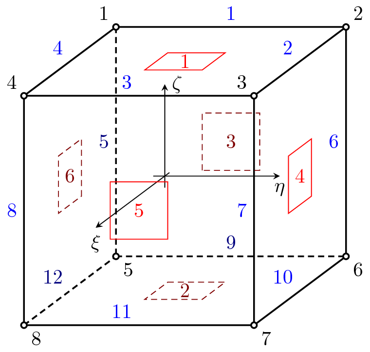
Figure 15: Geometry of tr_shell11 element.
Implementation of Discrete Kirchhoff Triangle (DKT) plate element. This element is suitable for thin plates, as the traswerse shear strain energy is neglected. The structure should be defined in x,y plane, nodes should be numbered anti-clockwise (positive rotation around z-axis). The element features are summarized in Table 23.
| Keyword | dktplate |
||||||||
| Description | 2D Discrete Kirchhoff Triangular plate element |
||||||||
| Specific parameters | - |
||||||||
| Unknowns | Three dofs (w-displacement, u and v - rotations) are required in each node. |
||||||||
| Approximation | Quadratic approximation of rotations, cubic approximation of displacement along the edges. Note: there is no need to define interpolation for displacement on the element. |
||||||||
| Integration | Default integration of all terms using three point formula. |
||||||||
| Features | Layered cross section support. |
||||||||
| CS properties | Cross section thickness is required. |
||||||||
| Loads | Body loads are supported. Boundary load support is beta. |
||||||||
| Output | On output, the generalized shell strain/force momentum vectors in global coordinate system are printed, with the following meaning:
where εx,εy,εxy are membrane in plane normal deformations, γzx,γxz are (out of plane and in plane) shear componets, κx,κy,κxy are curvatures, nx,ny,nxy,qxz,qyz are integral forces (normal and shear forces), and mx,my,mxy are bending moments. Please note, for example, that bending moment mx is defined as mx = ∫ σxz dz, so it acts along the y-axis and positive value causes tension in bottom layer. | ||||||||
| Nlgeo | 0. |
||||||||
| Status | Reliable |
||||||||
| Tests/Examples | |||||||||
| Reference | J.L.Batoz, K.J.Bathe, L.W.Ho: A study of three-node triangular plate bending elements, IJNME, 15(12):1771-1812, 1980 |
||||||||
Implementation of Discrete Kirchhoff Theory plate quad element (QDKT). This element is suitable for thin plates, as the traswerse shear strain energy is neglected. The structure should be defined in x,y plane, nodes should be numbered anti-clockwise (positive rotation around z-axis). The element features are summarized in Table 24.
| Keyword | qdktplate |
||||||||
| Description | 2D Discrete Kirchhoff Quad plate element |
||||||||
| Specific parameters | - |
||||||||
| Unknowns | Three dofs (w-displacement, u and v - rotations) are required in each node. |
||||||||
| Approximation | Quadratic approximation of rotations, cubic approximation of displacement along the edges. Note: there is no need to define interpolation for displacement on the element. |
||||||||
| Integration | Default integration of all bending terms using four point formula. |
||||||||
| Features | Layered cross section support. |
||||||||
| CS properties | Cross section thickness is required. |
||||||||
| Loads | Body loads are supported. |
||||||||
| Output | On output, the generalized shell strain/force momentum vectors in global coordinate system are printed, with the following meaning:
where εx,εy,εxy are membrane in plane normal deformations, γzx,γxz are (out of plane and in plane) shear componets, κx,κy,κxy are curvatures, nx,ny,nxy,qxz,qyz are integral forces (normal and shear forces), and mx,my,mxy are bending moments. Please note, for example, that bending moment mx is defined as mx = ∫ σxz dz, so it acts along the y-axis and positive value causes tension in bottom layer. | ||||||||
| Nlgeo | 0. |
||||||||
| Status | Reliable |
||||||||
| Tests/Examples | |||||||||
| Reference | J.L.Batoz, K.J.Bathe, L.W.Ho: A study of three-node triangular plate bending elements, IJNME, 15(12):1771-1812, 1980 |
||||||||
Implementation of constant curvature triangular element for plate analysis. Formulation based on Mindlin hypothesis. The structure should be defined in x,y plane. The nodes should be numbered anti-clockwise (positive rotation around z-axis). The element features are summarized in Table 25.
| Keyword | cctplate |
||||||||
| Description | 2D constant curvature triangular plate element |
||||||||
| Specific parameters | - |
||||||||
| Unknowns | Three dofs (w-displacement, u and v - rotations) are required in each node. |
||||||||
| Approximation | Linear approximation of rotations, quadratic approximation of displacement. |
||||||||
| Integration | Integration of all terms using one point formula. |
||||||||
| Features | Layered cross section support. |
||||||||
| CS properties | Cross section thickness is required. |
||||||||
| Loads | Body loads are supported. Boundary loads are not supported now. |
||||||||
| Output | On output, the generalized shell strain/force momentum vectors in global coordinate system are printed, with the following meaning:
where εx,εy,εxy are membrane in plane normal deformations, γzx,γxz are (out of plane and in plane) shear componets, κx,κy,κxy are curvatures, nx,ny,nxy,qxz,qyz are integral forces (normal and shear forces), and mx,my,mxy are bending moments. Please note, for example, that bending moment mx is defined as mx = ∫ σxz dz, so it acts along the y-axis and positive value causes tension in bottom layer. | ||||||||
| Nlgeo | 0. |
||||||||
| Status | Reliable |
||||||||
| Tests/Examples | tests/sm/patch_cct.in, tests/sm/patch_cct_02.in, tests/sm/patch200.in |
||||||||
Implementation of constant curvature triangular element for plate analysis. Formulation based on Mindlin hypothesis. The element could be arbitrarily oriented in space. The nodes should be numbered anti-clockwise (positive rotation around element normal). The element features are summarized in Table 26.
| Keyword | cctplate3d |
||||||||||||||||
| Description | Constant curvature triangular plate element in arbitray position |
||||||||||||||||
| Specific parameters | - |
||||||||||||||||
| Unknowns | Six dofs (u,v,w-displacements and u,v,w rotations) are in general required in each node. |
||||||||||||||||
| Approximation | Linear approximation of ratations, quadratic approximation of displacement. |
||||||||||||||||
| Integration | Integration of all terms using one point formula. |
||||||||||||||||
| Features | Layered cross section support. |
||||||||||||||||
| CS properties | Cross section thickness is required. |
||||||||||||||||
| Loads | Body loads are supported. Boundary loads are not supported now. |
||||||||||||||||
| Output | On output, the shell force (sf), shell strain (ss), shell momentum (sm), and shell curvature (sc) tensors in global coordinate system are printed as vector form with 6 components, with the following meaning:
where εx,εy,εz are membrane normal deformations, γzy,γzx,γxy are (out of plane and in plane) shear componets, κx,κy,κz,κyz,κxz,κxy are curvatures, nx,ny,nz,vyz,vxz,vxy are integral forces (normal and shear forces), and mx,my,mz,myz,mxz,mxy are bending moments. Please note, for example, that bending moment mx is defined as mx = ∫ σxz dz, so it acts along the y-axis and positive value causes tension in bottom layer. | ||||||||||||||||
| Nlgeo | 0. |
||||||||||||||||
| Status | Reliable |
||||||||||||||||
| Tests/Examples | |||||||||||||||||
Combination of CCT plate element (Mindlin hypothesis) with triangular plane stress element for membrane behavior. The element curvature can be specified. Although element requires generally six DOFs per node, no stiffness to local rotation along z-axis (rotation around element normal) is supplied. The element features are summarized in Table 27.
| Keyword | rershell |
||||||||||||||||
| Description | Simple shell based on combination of CCT plate element (Mindlin hypothesis) with triangular plane stress element. element can be arbitrary positioned in space. |
||||||||||||||||
| Specific parameters | - |
||||||||||||||||
| Unknowns | Six dofs (u,v,w-displacements and u,v,w rotations) are in general required in each node. Note, that although element it requires generally six DOFs per node, no stiffness to local rotation along z-axis (rotation around element normal) is supplied. |
||||||||||||||||
| Approximation | Linear approximation of ratations, quadratic approximation of displacement. |
||||||||||||||||
| Integration | Integration of all terms using one point formula. |
||||||||||||||||
| Features | Layered cross section support. |
||||||||||||||||
| CS properties | Cross section thickness is required. |
||||||||||||||||
| Loads | Body loads are supported. Boundary loads are not supported now. |
||||||||||||||||
| Output | On output, the shell force (sf), shell strain (ss), shell momentum (sm), and shell curvature (sc) tensors in global coordinate system are printed as vector form with 6 components, with the following meaning:
where εx,εy,εz are membrane normal deformations, γzy,γzx,γxy are (out of plane and in plane) shear componets, κx,κy,κz,κyz,κxz,κxy are curvatures, nx,ny,nz,vyz,vxz,vxy are integral forces (normal and shear forces), and mx,my,mz,myz,mxz,mxy are bending moments. Please note, for example, that bending moment mx is defined as mx = ∫ σxz dz, so it acts along the y-axis and positive value causes tension in bottom layer. | ||||||||||||||||
| Nlgeo | 0. |
||||||||||||||||
| Status | Reliable |
||||||||||||||||
| Tests/Examples | |||||||||||||||||
Combination of CCT3D plate element (Mindlin hypothesis) with triangular plane stress element for membrane behavior. It comes with complete set of 6 DOFs per node. The element features are summarized in Table 28.
| Keyword | tr_shell11 |
||||||||||||||||
| Description | Triangular shell element combining CCT3D plate element (Mindlin hypothesis) with triangular plane stress element with rotational DOFs |
||||||||||||||||
| Specific parameters | - |
||||||||||||||||
| Unknowns | Six dofs (u,v,w-displacements and u,v,w rotations) are in general required in each node. |
||||||||||||||||
| Approximation | See description of cct and trplanstrrot elements |
||||||||||||||||
| Integration | Four point integration, reduced integration of strain associated to normal rotation and shear terms. |
||||||||||||||||
| Features | Layered cross section support. |
||||||||||||||||
| CS properties | Cross section thickness is required. |
||||||||||||||||
| Loads | Body loads are supported. Boundary loads are supported (only surface loads). |
||||||||||||||||
| Output | On output, the shell force (sf), shell strain (ss), shell momentum (sm), and shell curvature (sc) tensors in global coordinate system are printed as vector form with 6 components, with the following meaning:
where εx,εy,εz are membrane normal deformations, γzy,γzx,γxy are (out of plane and in plane) shear componets, κx,κy,κz,κyz,κxz,κxy are curvatures, nx,ny,nz,vyz,vxz,vxy are integral forces (normal and shear forces), and mx,my,mz,myz,mxz,mxy are bending moments. Please note, for example, that bending moment mx is defined as mx = ∫ σxz dz, so it acts along the y-axis and positive value causes tension in bottom layer. | ||||||||||||||||
| Nlgeo | 0. |
||||||||||||||||
| Status | Reliable |
||||||||||||||||
| Tests/Examples | |||||||||||||||||
Combination of thin-plate DKT plate element with plane stress element (TrPlanestressRotAllman). This element comes with complete set of 6 DOFs per node. The element features are summarized in Table 29.
| Keyword | tr_shell02 |
||||||||||||||||
| Description | Triangular shell element combining DKT plate element with triangular plane stress element with rotational DOFs |
||||||||||||||||
| Specific parameters | - |
||||||||||||||||
| Unknowns | Six dofs (u,v,w-displacements and u,v,w rotations) are in general required in each node. |
||||||||||||||||
| Approximation | See description of cct and trplanstrrot elements |
||||||||||||||||
| Integration | 4 integration points necessary, use ”NIP 4” in element record. |
||||||||||||||||
| CS properties | Cross section thickness is required. |
||||||||||||||||
| Loads | Body loads are supported. Boundary loads are supported (only surface loads). |
||||||||||||||||
| Output | On output, the shell force (sf), shell strain (ss), shell momentum (sm), and shell curvature (sc) tensors in global coordinate system are printed as vector form with 6 components, with the following meaning:
where εx,εy,εz are membrane normal deformations, γzy,γzx,γxy are (out of plane and in plane) shear componets, κx,κy,κz,κyz,κxz,κxy are curvatures, nx,ny,nz,vyz,vxz,vxy are integral forces (normal and shear forces), and mx,my,mz,myz,mxz,mxy are bending moments. Please note, for example, that bending moment mx is defined as mx = ∫ σxz dz, so it acts along the y-axis and positive value causes tension in bottom layer. | ||||||||||||||||
| Nlgeo | 0. |
||||||||||||||||
| Status | - | ||||||||||||||||
| Note | Works only with linear material models, as bending and membrane actions are uncoupled |
||||||||||||||||
| Tests/Examples | |||||||||||||||||
This class implements an quadrilateral, bilinear, four-node Mindlin plate. This type of element exhibit strong shear locking (thin plates exhibit almost no bending). Implements the lumped mass matrix. The element features are summarized in Table 30.
| Keyword | quad1mindlin |
||||||||
| Description | Quadrilateral, bilinear, four-node Mindlin plate |
||||||||
| Specific parameters | [NIP #(in)] |
||||||||
| Unknowns | Three dofs (w-displacement, u and v - rotation) are required in each node. |
||||||||
| Approximation | Linear for all unknowns. |
||||||||
| Integration | Default uses 4 integration points. No reduced integration is used, as it causes numerical problems. |
||||||||
| Features | Layered cross section support. |
||||||||
| CS properties | Cross section thickness is required. |
||||||||
| Loads | Dead weight loads, and edge loads are supported. |
||||||||
| Output | On output, the generalized shell strain/force momentum vectors in global coordinate system are printed, with the following meaning:
where εx,εy,εxy are membrane in plane normal deformations, γzx,γxz are (out of plane and in plane) shear componets, κx,κy,κxy are curvatures, nx,ny,nxy,qxz,qyz are integral forces (normal and shear forces), and mx,my,mxy are bending moments. Please note, for example, that bending moment mx is defined as mx = ∫ σxz dz, so it acts along the y-axis and positive value causes tension in bottom layer. | ||||||||
| Nlgeo | 0. |
||||||||
| Reference | [1] |
||||||||
| Status | Experimental |
||||||||
| Tests/Examples | |||||||||
This class implements a triangular, quadratic, six-node shell element. The element is a so-called seven parameter shell with seven dofs per node – a displacement field (3 dofs), an extensible director field (3 dofs) and a seventh dof representing inhomogenous thickness strain. This last parameter is included in the model in order to deal with volumetric/Poisson lock effects.
The element features are summarized in Table 30.
| Keyword | tr2shell7 |
| Description | Triangular, quadratic, six-node shell with 7 dofs/node |
| Specific parameters | [NIP #(in)] |
| Unknowns | Seven dofs (displacement in u, v and w-direction; change in director field in u, v and w-direction; and inhomgenous thickness stretch) are required in each node. |
| Approximation | Quadratic for all unknowns. |
| Integration | Default uses 6 integration points in the midsurface plane. Number of integration points in the thickness direction is determined by the Layered cross section. |
| Features | Layered cross section support. |
| CS properties | This element must be used with a Layered cross section. |
| Loads | Edge loads, constant pressure loads and surface loads are supported. |
| Nlgeo | Not applicable. The implementation is for large defomrations and hence geometrical nonlinearities will always be present, regardless the value of Nlgeo. |
| Reference | [3] |
| Status | Experimental |
| Tests/Examples | |
A four-node quadrilateral shell element formulated using three-dimensional continuum mechanics theory degenerated to shell behaviour. The element is applicable to thick and thin shells as the “mixed interpolation of tensorial components” (MITC) approach is used to remove shear locking. The implementation is based on the following paper: Dvorkin, E.N., Bathe, K.J.: A continuum mechanics based four-node shell element for general non-linear analysis, Eng.Comput., Vol.1, 77-88, 1984.
Although element requires generally six DOFs per node, no stiffness to local rotation along z-axis (rotation around director vector) is supplied. The element features are summarized in Table 32.
| Keyword | mitc4shell |
|||||||||||||||||||||||||||||||||||||
| Description | Quadrilateral, bilinear, four-node shell element using the MITC technique. |
|||||||||||||||||||||||||||||||||||||
| Specific parameters | [NIP #(in)] [NIPZ #(in)] [directorType #(in)] |
|||||||||||||||||||||||||||||||||||||
| Parameters | NIP: allows to set the number of integration points in local x-y plane (default 4). |
|||||||||||||||||||||||||||||||||||||
| NIPZ: allows to set the number of integration points in local z-direction (default 2). |
||||||||||||||||||||||||||||||||||||||
| directorType: allows to set director vectors. Director vectors can be set as normal to the plane (directorType = 0, default), or calculated for each node as an average of neighbouring elements of same crosssection (directorType = 1), or can be specified at crosssection (directorType =2). |
||||||||||||||||||||||||||||||||||||||
| Unknowns | Six dofs (u,v,w-displacements and u,v,w rotations) are in general required in each node. Note, that although element requires generally six DOFs per node, no stiffness to local rotation along z-axis (rotation around director vector) is supplied. |
|||||||||||||||||||||||||||||||||||||
| Approximation | Linear approximation of displacements and rotations. |
|||||||||||||||||||||||||||||||||||||
| Integration | Integration of all terms using Gauss integration formula in 8 points (default) or specified using NIP and NIPZ parameters. |
|||||||||||||||||||||||||||||||||||||
| Features | Variable cross section support. |
|||||||||||||||||||||||||||||||||||||
| CS properties | Cross section thickness is required (measured along director vector). Director vectors components may be specified [directorx #(in)][directory #(in)][directorz #(in)] in case of directorType 2. |
|||||||||||||||||||||||||||||||||||||
| Loads | Body and boundary loads are supported. |
|||||||||||||||||||||||||||||||||||||
| Output | On output, the shell force (sf), shell momentum (sm), shell strain (ss), shell curvature (sc), strain (ε), and stress (σ) tensors in global coordinate system are printed as vector form with 6 components, with the following meaning:
where nx,ny,nz,vyz,vxz,vxy are integral forces (normal and shear forces), and mx,my,mz,myz,mxz,mxy are bending moments, εx,εy,εz are membrane normal deformations, γzy,γzx,γxy are (out of plane and in plane) shear componets, κx,κy,κz,κyz,κxz,κxy are curvatures. Please note, for example, the bending moment mx is defined as mx = ∫ σxz dz, so it acts along the y-axis and positive value causes tension in bottom layer (positive z-coordinate). The shell force (sf), shell momentum (sm), shell strain (ss), and shell curvature (sc) tensors are evaluated at the midplane of the element (thus are constant along the thickness) while the strain (ε), and stress (σ) tensors are evaluated at each Gausspoint. | |||||||||||||||||||||||||||||||||||||
| Nlgeo | 0. |
|||||||||||||||||||||||||||||||||||||
| Status | - |
|||||||||||||||||||||||||||||||||||||
| Tests/Examples | tests/sm/patch_mitc4.in, tests/sm/patch_mitc4_02.in, tests/sm/scordelis_mitc4.in |
|||||||||||||||||||||||||||||||||||||
This class implements an quadrilateral, bilinear, four-node plate subsoil element. Typically this element is combined with suitable plate element with quadrilateral geometry to model plate element on (elastic) subsoill foundation, but it can be used alone. The element geometry should be define in xy plane. The element features are summarized in Table 33.
| Keyword | quad1plateSubsoil |
| Description | Quadrilateral, bilinear, four-node sub-soil plate element |
| Specific parameters |
|
| Unknowns | One dof (w-displacement) is required in each node. |
| Approximation | Linear for transwersal displacement. |
| Integration | 4 integration points. |
| Loads | Surface load support. |
| Note | Requires material model with 2dPlateSubSoil mode support. |
| Reference | [2] |
| Tests/Examples | |
This class implements an quadrilateral, bilinear, four-node plate subsoil element. Typically this element is combined with suitable plate element with quadrilateral geometry to model plate element on (elastic) subsoill foundation, but it can be used alone. The element geometry should be define in xy plane. The element features are summarized in Table 33.
| Keyword | tria1platesubsoil |
| Description | Tringular, three-node sub-soil plate element with linear interpolation |
| Specific parameters |
|
| Unknowns | One dof (w-displacement) is required in each node. |
| Approximation | Linear for transwersal displacement. |
| Integration | 1 integration points. |
| Loads | Surface load support. |
| Note | Requires material model with 2dPlateSubSoil mode support. |
| Reference | [2] |
| Tests/Examples | |